A wiring diagram is one of the most important visual tools used in electrical and electronic work. At its core, it is a structured illustration that shows how different electrical components are connected within a system and how electrical current is expected to flow between them. Instead of relying on guesswork or memory, professionals use these diagrams as a clear reference that reduces mistakes and improves safety. Although they may look technical at first glance, wiring diagrams are essentially organized maps of electrical relationships.
In everyday life, almost every powered device or system depends on a wiring design in the background. Whether it is a simple household light circuit or a large industrial control system, wiring diagrams define how power is distributed and how components interact. They serve as a universal language that electricians, engineers, and technicians can all understand regardless of location or project type.
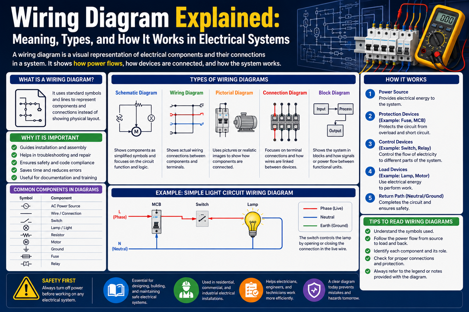
At a basic level, a wiring diagram is built around clarity and structure. It breaks down complex electrical systems into smaller, understandable parts. Each component is represented using standardized symbols rather than realistic drawings. This symbolic representation makes diagrams easier to read and allows professionals to quickly identify what each part does without needing detailed illustrations. For example, a switch is shown with a simple symbol rather than a physical depiction, while power sources, resistors, and loads each have their own recognized representation.
The flow of electricity is another key concept shown in wiring diagrams. Lines are used to represent wires, and these lines show how current moves through the system. In most cases, a straight line indicates a direct connection, while branching lines show multiple pathways. This structure helps users understand how electricity is distributed from a source to different components and how those components influence each other.
Beyond symbols and lines, labeling plays a major role in wiring diagrams. Each element is usually marked with a name, number, or identifier that explains its function or position. This helps eliminate confusion, especially in complex systems where multiple similar components are present. Labels also make troubleshooting easier because technicians can quickly locate the exact part of the circuit they need to inspect or replace.
Wiring diagrams are commonly divided into several types based on their purpose and level of detail. One of the most basic forms is the schematic diagram. This type focuses on the logical structure of a circuit rather than its physical arrangement. It shows how components are connected in principle, making it easier to understand how the system functions as a whole. Schematics are widely used during the design phase because they provide a conceptual view of electrical behavior.
Another type is the circuit diagram, which offers more detail compared to schematics. Circuit diagrams show actual connections and may include more information about physical layout and wiring paths. These diagrams are particularly useful during installation and repair work because they provide a closer representation of how components are arranged in real environments.
There are also simplified diagrams that focus on ease of understanding rather than technical precision. These are often used for educational purposes or basic installations where full technical detail is not necessary. Regardless of the type, all wiring diagrams aim to communicate electrical relationships clearly and consistently.
One of the key strengths of wiring diagrams is their ability to reduce complexity. Electrical systems can become extremely complicated when multiple devices, circuits, and connections are involved. Without a diagram, understanding how everything works together would be nearly impossible. Wiring diagrams solve this problem by breaking down the system into a visual format that is easy to follow step by step.
In addition, wiring diagrams play an important role in ensuring safety. Electrical systems can be dangerous if not handled correctly, and incorrect wiring can lead to short circuits, equipment damage, or even fire hazards. By following a properly designed diagram, technicians can ensure that every connection is made correctly and according to specifications. This reduces the risk of errors and helps maintain safe operating conditions.
The importance of standardization in wiring diagrams cannot be overlooked. Across industries, standardized symbols and conventions ensure that diagrams are universally understandable. This means a technician in one country can interpret a diagram created in another without confusion. Standardization also supports collaboration, especially in large projects involving multiple teams.
Even in simple residential applications, wiring diagrams provide significant value. Home lighting systems, ceiling fans, and electrical outlets all rely on structured wiring layouts. For example, a basic lighting circuit may involve switches, power sources, and lighting fixtures connected in a specific configuration. A wiring diagram clearly shows how these elements interact, making installation and maintenance more straightforward.
As electrical systems evolve, wiring diagrams continue to remain relevant. They are not limited to traditional electrical systems but also apply to modern electronic devices and automated systems. From household appliances to industrial machinery, the principle remains the same: clear visualization of electrical connections leads to better understanding and control.
Wiring diagrams act as the foundation for all electrical design and maintenance work. Without them, managing even simple systems would become inefficient and error-prone. Their combination of symbols, structured lines, and organized layout creates a powerful communication tool that supports accuracy, safety, and efficiency in electrical work of all kinds.
The Role of Wiring Diagrams in Modern Technology and Network Infrastructure
In today’s interconnected world, wiring diagrams have moved far beyond traditional electrical systems. They now play a critical role in modern technology environments, especially in networking, data centers, and communication systems. As digital infrastructure becomes more complex, the need for clear and organized wiring documentation has become more important than ever.
One of the most significant areas where wiring diagrams are used is network infrastructure. Modern networks depend on countless physical connections between devices such as routers, switches, servers, and end-user equipment. Without a structured visual representation, managing these connections would be extremely difficult. Wiring diagrams provide a clear map of how data flows between devices and how each component contributes to the overall system.
In local and wide-area networks, wiring diagrams help define how devices communicate across different locations. They illustrate the pathways through which data travels, ensuring that network administrators understand how systems are connected. This is especially important in large organizations where multiple buildings or departments rely on shared communication systems.
Switches and routers are central to network operations, and wiring diagrams help show their relationships within the system. These diagrams illustrate how traffic is directed, how devices are segmented, and how different network layers interact. By visualizing these connections, technicians can identify potential bottlenecks or configuration issues before they affect performance.
Patch panels are another critical element in structured cabling environments. They act as centralized points where multiple network cables converge. Wiring diagrams help track these connections, making it easier to manage changes, perform maintenance, and troubleshoot issues. In large-scale installations, this level of organization is essential for maintaining efficiency.
Data centers represent one of the most complex environments where wiring diagrams are essential. These facilities contain thousands of interconnected components, including servers, storage systems, and power distribution units. A single error in connectivity can impact performance or cause system failures. Wiring diagrams provide a detailed overview of how each component is connected and how power and data flow through the system.
Within data centers, server racks are carefully organized using structured wiring plans. Each server must be connected to power and network systems in a precise manner. Wiring diagrams help map these connections, ensuring that equipment is installed correctly and can be maintained efficiently. They also help plan future expansions by showing available capacity and connection points.
Power distribution is another critical aspect of data center operations. Wiring diagrams illustrate how electricity is distributed across multiple devices using power distribution units. This ensures that no single circuit is overloaded and that all equipment receives stable and reliable power. Without this level of planning, system reliability would be at risk.
Cooling systems also benefit from wiring diagrams, especially in large facilities where temperature control is essential for performance. These diagrams show how cooling units are distributed and how they interact with airflow systems. Proper cooling is necessary to prevent overheating and ensure long-term system stability.
Telecommunication systems rely heavily on structured wiring as well. Traditional telephone networks, modern voice-over-IP systems, and fiber optic communication lines all require detailed diagrams to manage connectivity. These systems often span large geographical areas, making accurate documentation essential for maintenance and troubleshooting.
Fiber optic networks, in particular, require precise mapping due to the high-speed nature of data transmission. Wiring diagrams help show how fiber cables are routed, connected, and distributed across different network nodes. This ensures that communication remains fast and reliable.
In modern enterprise environments, wireless systems are also integrated with wired infrastructure. Even though wireless communication does not rely on physical cables for data transmission, it still depends on wired backbones. Wiring diagrams help show how wireless access points are connected to the core network, ensuring seamless connectivity across the entire system.
Another important application of wiring diagrams in technology is automation and smart systems. Industrial automation systems use complex networks of sensors, controllers, and actuators. Wiring diagrams help engineers understand how these components interact and ensure that automated processes function correctly.
As technology continues to evolve, wiring diagrams remain a critical part of system design and management. They provide a structured way to understand complex networks, making it easier to build, maintain, and expand modern infrastructure. Without them, managing today’s interconnected systems would be significantly more challenging and error-prone.
Designing, Interpreting, and Evolving Wiring Diagrams in Practice
Creating and interpreting wiring diagrams is both a technical skill and a structured thinking process. While the diagrams themselves may appear static, they represent dynamic systems that require careful planning, accurate documentation, and ongoing updates. Understanding how to work with these diagrams is essential for anyone involved in electrical or network-related fields.
The process of designing a wiring diagram begins with understanding the system requirements. Before any lines are drawn, the purpose of the system must be clearly defined. This includes identifying all components, their functions, and how they are expected to interact. Once this foundation is established, the diagram can be built step by step to reflect those relationships.
Modern design often relies on digital tools that allow for precise diagram creation. These tools help organize components, maintain consistency in symbols, and reduce human error. They also make it easier to modify diagrams when systems change, which is a common occurrence in both electrical and network environments.
One of the most important aspects of diagram design is accuracy. Every connection must reflect real-world implementation. Even a small mistake in a wiring diagram can lead to system failures or safety risks. For this reason, professionals follow strict standards when creating diagrams, ensuring that symbols, lines, and labels are used correctly and consistently.
Organization is equally important. A well-designed wiring diagram is structured in a way that makes it easy to follow the flow of electricity or data. Components are arranged logically, often following the direction of flow from source to destination. This makes the diagram easier to read and reduces confusion during installation or maintenance.
Interpreting wiring diagrams requires a different set of skills. Instead of creating the diagram, the focus is on understanding what it represents. This begins by identifying individual components and recognizing their symbols. Once the components are understood, the next step is tracing connections to see how they interact within the system.
Reading wiring diagrams also involves understanding pathways and relationships. Following the flow of connections helps reveal how systems operate as a whole. This is especially useful when diagnosing issues, as technicians can trace the flow to identify where problems may be occurring.
Troubleshooting using wiring diagrams is a practical application of interpretation skills. When a system fails, the diagram serves as a guide to isolate potential causes. By following connections step by step, technicians can narrow down the source of the issue and apply the correct fix. This approach saves time and reduces unnecessary guesswork.
Wiring diagrams also evolve over time. As systems are upgraded or modified, diagrams must be updated to reflect new configurations. This ensures that documentation remains accurate and continues to serve as a reliable reference. Outdated diagrams can lead to confusion and errors, especially in large systems with frequent changes.
Another important aspect of modern wiring diagrams is integration with advanced technologies. In some environments, digital models of systems are created to simulate real-world behavior. These models combine wiring diagrams with real-time data, allowing for better monitoring and planning. This integration supports predictive maintenance and improves system reliability.
Standardization continues to play a major role in diagram evolution. As systems become more global and interconnected, standardized symbols and formats ensure that diagrams remain universally understandable. This consistency is especially important in multinational projects where teams from different regions collaborate on the same infrastructure.
Wiring diagrams also support future planning. By analyzing existing layouts, engineers can identify opportunities for expansion or improvement. This helps ensure that systems remain scalable and adaptable as technology continues to advance.
In modern practice, wiring diagrams are no longer just static documents. They are dynamic tools that support design, operation, maintenance, and future development. Their role continues to expand as systems become more complex and interconnected, making them an essential part of both traditional and advanced technical environments.
Advanced Concepts, Industry Evolution, and the Future of Wiring Diagrams
At advanced levels of engineering, wiring diagrams are no longer treated as simple instructional visuals. Instead, they become structured engineering documents that define how entire systems are intended to function across electrical, electronic, and communication layers. In complex environments, these diagrams are not just used during installation but throughout the entire lifecycle of a system, including design validation, testing, maintenance, and upgrades.
Engineers often approach wiring diagrams as part of a larger system model. Rather than focusing only on individual connections, they analyze how power distribution, signal integrity, and system behavior interact. This broader perspective helps ensure that electrical systems do not simply work in isolation but perform reliably under real-world conditions such as load variations, environmental stress, and operational scaling.
At this level, diagrams also reflect redundancy planning and fault tolerance strategies. Critical systems, such as those used in industrial control or communication infrastructure, often include backup pathways. These alternate routes are carefully mapped in wiring diagrams so that if one connection fails, another can immediately take over. This level of planning requires precision, as even small inaccuracies can lead to system instability.
Another important aspect is modular design representation. Complex systems are often broken into smaller functional units, and wiring diagrams reflect these divisions. Each module is represented as a self-contained block that connects to others through defined interfaces. This modular approach makes it easier to update or replace parts of a system without redesigning everything from scratch.
In advanced engineering environments, wiring diagrams also serve as documentation for compliance and verification. They are reviewed during system certification processes to ensure that designs meet required operational and safety standards. This makes them not only technical tools but also legal and regulatory documents in many industries.
Precision Standards and Global Electrical Conventions
As electrical and electronic systems have become globalized, standardized conventions in wiring diagrams have become essential. Without consistent rules, interpreting diagrams across different countries, industries, or manufacturers would be extremely difficult. Standardization ensures that a symbol representing a switch, resistor, or data connection means the same thing everywhere.
These conventions define not only symbols but also line styles, labeling systems, and organizational structures. For example, consistent use of line types helps distinguish between power lines, signal lines, and control pathways. Similarly, standardized labeling ensures that components can be traced easily across large systems without confusion.
Global standards also regulate how safety elements are represented. Grounding symbols, protective devices, and isolation components must be clearly identified in all diagrams. This is especially important in high-voltage or industrial environments where incorrect interpretation can lead to serious hazards.
Another important aspect of standardization is hierarchical structuring. Large systems are often represented across multiple levels of diagrams, from high-level overviews to detailed circuit layouts. Each level must align logically with the others so that engineers can move between abstraction levels without losing context.
Standardization also improves collaboration. In multinational projects, teams often work across different time zones and technical backgrounds. A shared diagram language ensures that all participants interpret systems consistently, reducing miscommunication and design errors.
Over time, these conventions continue to evolve as new technologies emerge. Modern systems now include digital signals, fiber communication paths, and automated control networks, all of which require expanded diagram standards. Despite these changes, the core principle remains the same: clarity and consistency in representing electrical relationships.
Wiring Diagrams in Automated and Smart Environments
With the rise of automation and intelligent systems, wiring diagrams have taken on a new role in supporting dynamic and responsive environments. Modern systems such as smart buildings, automated factories, and intelligent energy grids depend on highly interconnected networks of sensors, controllers, and communication devices.
In these environments, wiring diagrams are used not only to show physical connections but also to represent logical relationships between automated components. A sensor may trigger a controller, which then activates an actuator, and all of these interactions must be clearly mapped. This level of complexity requires diagrams that go beyond static representation and reflect system behavior.
Smart environments also introduce the concept of real-time responsiveness. Systems are constantly collecting data and adjusting operations based on conditions. Wiring diagrams help engineers understand how information flows through these systems, ensuring that responses occur correctly and efficiently.
In energy systems, especially modern electrical grids, wiring diagrams help manage distributed generation sources such as solar panels and wind systems. These systems require careful coordination to balance supply and demand. Diagrams illustrate how energy flows between producers, storage units, and consumers, ensuring stability across the entire network.
Automation in industrial environments also relies heavily on wiring documentation. Machines are often controlled by programmable systems that depend on precise electrical and data connections. Wiring diagrams ensure that these systems are installed correctly and that signals reach their intended destinations without interference.
As systems become more intelligent, wiring diagrams are increasingly integrated with software-based control systems. This allows engineers to simulate and adjust configurations before physical implementation, reducing risk and improving efficiency.
Diagnostic Intelligence and Fault Analysis Using Diagrams
One of the most critical uses of wiring diagrams is in fault diagnosis and system troubleshooting. When a system fails or behaves unexpectedly, wiring diagrams serve as the primary reference for identifying the source of the issue. They allow technicians to trace connections systematically and isolate faulty components.
Fault analysis begins by identifying symptoms and then mapping them back through the diagram. By following the flow of electricity or data, technicians can narrow down potential failure points. This structured approach is far more efficient than random testing or trial-and-error methods.
In complex systems, faults may not be caused by a single point of failure but by interactions between multiple components. Wiring diagrams help reveal these relationships by showing how different parts of a system influence each other. This makes it easier to identify indirect causes of malfunction.
Another important aspect of diagnostic use is continuity verification. Technicians often use diagrams to confirm that all connections are intact and properly routed. This is especially important in systems where multiple cables or signals run in parallel paths.
Modern diagnostic processes also involve comparing real system behavior with diagram-based expectations. If a system is not behaving as shown in the diagram, it indicates a potential wiring issue, configuration error, or component failure. This comparison-based approach improves accuracy and reduces downtime.
In large infrastructure systems, diagnostic workflows rely heavily on segmented diagrams. Instead of analyzing the entire system at once, technicians focus on individual sections. This modular approach simplifies troubleshooting and makes complex systems more manageable.
Integration with Modern Design Tools and Digital Modeling Systems
The way wiring diagrams are created and used has changed significantly with the introduction of advanced digital tools. Traditional hand-drawn diagrams have largely been replaced by computer-based design systems that offer precision, scalability, and real-time collaboration.
Modern design tools allow engineers to build diagrams using standardized component libraries. These libraries ensure that symbols remain consistent and accurate across different projects. They also reduce the time required to create complex system layouts.
One of the most important advancements is the integration of wiring diagrams with simulation environments. Engineers can now test how a system will behave before it is physically built. This includes simulating electrical loads, signal flow, and potential failure conditions.
Digital systems also support automatic error detection. If a connection is missing, incorrect, or violates design rules, the software can flag the issue immediately. This reduces the likelihood of design flaws reaching the implementation stage.
Another major development is the concept of digital twins. A digital twin is a virtual representation of a physical system that mirrors its structure and behavior. Wiring diagrams form the foundation of these digital models, providing the structural blueprint for simulation and monitoring.
Collaboration has also improved significantly. Multiple engineers can work on the same diagram simultaneously, regardless of location. Changes are updated in real time, ensuring that all team members are working with the most current version.
These tools also support version tracking, allowing teams to monitor changes over time. This is especially useful in long-term projects where systems evolve through multiple stages of development and maintenance.
Industry-Specific Adaptations of Wiring Systems
Different industries adapt wiring diagrams to meet their unique operational requirements. In aerospace systems, for example, diagrams must account for extreme conditions such as vibration, temperature variation, and high reliability requirements. Every connection is carefully documented to ensure safety and performance under all conditions.
In the automotive industry, wiring diagrams have become increasingly complex due to the integration of electronic control systems. Modern vehicles contain numerous sensors, control units, and communication networks. Wiring diagrams help manage these systems and ensure that all components interact correctly.
Industrial control systems rely heavily on wiring diagrams to coordinate machinery, production lines, and automated processes. These environments require high precision and reliability, as even minor wiring errors can disrupt entire operations.
In communication infrastructure, wiring diagrams support the design of large-scale networks that include fiber optics, wireless systems, and distributed nodes. These diagrams help ensure that data flows efficiently and that network performance remains stable.
Each industry adapts wiring documentation to match its specific needs, but the underlying principle remains consistent: clear representation of electrical and logical relationships to ensure system reliability.
Common Challenges in Complex Wiring Systems
As systems become more complex, wiring diagrams face several challenges. One of the most common issues is overcrowding. When too many components are included in a single diagram, readability decreases, making it difficult to interpret relationships clearly.
Another challenge is maintaining accuracy over time. As systems evolve, diagrams must be continuously updated. If updates are not properly managed, discrepancies between real systems and documented diagrams can occur, leading to confusion and errors.
Ambiguity in representation is another issue. Even with standardized symbols, complex systems can sometimes be difficult to interpret without additional context. This can lead to miscommunication between design and maintenance teams.
Scaling is also a major challenge. As systems grow, diagrams must expand without losing clarity. This often requires breaking large systems into multiple interconnected diagrams, which must remain consistent with each other.
Despite these challenges, careful planning, structured documentation, and modern design tools help reduce risks and maintain diagram effectiveness.
Future Direction of Wiring Visualization Systems
The future of wiring diagrams is closely tied to advancements in digital technology and intelligent systems. As automation, artificial intelligence, and real-time monitoring continue to develop, wiring diagrams are expected to become more interactive and adaptive.
Instead of static images, future diagrams may function as dynamic models that update automatically based on system conditions. This would allow engineers to see real-time changes in system behavior directly within the diagram environment.
Integration with artificial intelligence may also improve diagnostic capabilities. Systems could automatically analyze wiring structures, detect potential issues, and suggest optimizations without manual intervention.
Augmented visualization technologies may further enhance how wiring systems are understood. Engineers could potentially view layered system information in immersive environments, allowing for deeper insight into complex connections.
As systems continue to grow in scale and complexity, wiring diagrams will remain a fundamental tool, evolving alongside technology while maintaining their core purpose of clarity and structure in electrical and system design.
Wiring Diagrams as Living Operational Documents
In practical engineering environments, wiring diagrams are not static references that are created once and forgotten. Instead, they function as living operational documents that evolve continuously alongside the systems they represent. Every modification, upgrade, repair, or expansion within an electrical or networked system must be reflected in its corresponding wiring documentation to maintain accuracy and reliability.
This ongoing evolution makes wiring diagrams central to long-term system governance. They become the authoritative source of truth for understanding how infrastructure is structured at any given moment. Without this updated documentation, organizations risk creating gaps between actual physical systems and recorded designs, which can lead to serious operational inefficiencies or safety hazards.
In many industries, maintaining updated wiring documentation is treated as a formal responsibility rather than an optional task. Engineering teams, maintenance crews, and system administrators all rely on accurate diagrams to ensure continuity of operations. Even small undocumented changes can accumulate over time and create significant confusion during troubleshooting or expansion efforts.
The concept of a living document also extends to version tracking. Each revision of a wiring diagram represents a snapshot of the system at a specific point in time. Proper version control allows teams to trace changes, understand design decisions, and revert to earlier configurations if needed. This historical record is especially valuable in complex environments where systems undergo frequent modifications.
Human Factors and Cognitive Load in Diagram Interpretation
While wiring diagrams are designed to simplify complexity, they also introduce challenges related to human cognition. Interpreting large-scale diagrams requires concentration, pattern recognition, and the ability to mentally map abstract symbols to real-world components. In high-pressure environments, such as industrial maintenance or emergency repair situations, cognitive overload can become a serious issue.
One of the key human factors in wiring interpretation is visual density. When too many connections, symbols, and labels are placed in a confined space, readability decreases significantly. This can lead to misinterpretation or oversight, especially when technicians are working under time constraints.
To reduce cognitive strain, diagrams are often segmented into logical layers. Instead of presenting an entire system in a single view, engineers divide it into functional sections. This allows individuals to focus on smaller portions of the system without losing context. For example, a power distribution system might be separated into generation, transmission, and load sections.
Another important factor is familiarity with standardized symbols. Even though global conventions exist, technicians with varying levels of experience may interpret symbols differently. This is why training and standardization are critical in ensuring consistent understanding across teams.
Environmental conditions also affect interpretation. Poor lighting, time pressure, and high-stress situations can reduce accuracy in reading diagrams. In such cases, clear labeling and simplified layouts become essential tools for reducing human error.
Safety Engineering and Risk Prevention Through Wiring Design
Safety is one of the most critical aspects of wiring system design. Electrical systems inherently carry risks, including short circuits, overloads, fire hazards, and equipment damage. Wiring diagrams play a central role in identifying and mitigating these risks before systems are physically implemented.
One of the key safety principles embedded in wiring design is isolation. Sensitive components are often separated from high-power circuits to prevent interference or accidental damage. Wiring diagrams clearly indicate these separations, ensuring that installation teams follow safe routing practices.
Grounding and earthing systems are also carefully represented. Proper grounding is essential for protecting both equipment and personnel from electrical faults. Diagrams ensure that grounding connections are correctly distributed throughout the system and that no critical component is left unprotected.
Another important safety aspect is load balancing. Electrical systems must be designed to distribute power evenly across circuits to prevent overheating or failure. Wiring diagrams help engineers calculate and visualize load distribution, ensuring that no single circuit is overloaded beyond its capacity.
Safety engineering also involves redundancy planning. In critical systems such as hospitals, industrial plants, or communication networks, backup circuits are often included to maintain operation in case of failure. Wiring diagrams map these redundant pathways, ensuring that they function seamlessly when activated.
Isolation switches, circuit breakers, and protective devices are also clearly represented in diagrams. These elements act as safeguards that automatically disconnect power during abnormal conditions. Their correct placement is essential for system safety, and wiring diagrams ensure they are integrated properly into the overall design.
Installation Practices and Field Implementation Challenges
Translating wiring diagrams into physical installations is a complex process that requires precision, coordination, and technical expertise. While diagrams provide a blueprint, real-world conditions often introduce variables that must be managed carefully.
One of the most common challenges during installation is environmental variability. Construction sites, industrial facilities, and outdoor environments may not match ideal design assumptions. Installers often need to adapt wiring routes while still adhering to the principles outlined in the diagram.
Cable management is another critical aspect of installation. Wires must be routed in a way that prevents tangling, overheating, or physical damage. Proper spacing, labeling, and bundling are essential to maintaining system organization and ensuring future accessibility.
In large installations, coordination between multiple teams becomes necessary. Electrical, networking, and mechanical teams often work simultaneously in shared spaces. Wiring diagrams serve as a common reference point to ensure that all teams align their work without conflict.
Another challenge is ensuring consistency between planned and actual installations. Even small deviations from the diagram must be documented immediately. Failure to do so can create discrepancies that become difficult to resolve later during maintenance or troubleshooting.
Testing and verification are also essential parts of the installation process. Once wiring is completed, systems must be tested to ensure that all connections function as intended. Wiring diagrams guide these tests by defining expected behavior and connection pathways.
Maintenance Lifecycle and Long-Term System Reliability
Wiring systems are not static; they require ongoing maintenance to ensure long-term reliability. Over time, components degrade, systems expand, and operational demands change. Wiring diagrams play a central role in managing this lifecycle.
Preventive maintenance is one of the most important aspects of system longevity. Instead of waiting for failures, technicians regularly inspect and test components based on information provided in wiring diagrams. This helps identify potential issues before they escalate into serious problems.
Corrective maintenance relies heavily on diagrams as well. When failures occur, technicians use wiring documentation to trace faults and restore functionality. Without accurate diagrams, troubleshooting becomes significantly slower and more error-prone.
Predictive maintenance is an emerging approach that uses system data to anticipate failures before they occur. Wiring diagrams support this process by providing a structural framework for analyzing system behavior and identifying weak points.
Lifecycle management also includes periodic system upgrades. As technology evolves, older components may be replaced with newer, more efficient alternatives. Wiring diagrams must be updated accordingly to reflect these changes and ensure continued accuracy.
Documentation consistency is essential throughout the lifecycle. If multiple versions of diagrams exist without proper coordination, confusion can arise during maintenance operations. Centralized documentation control helps prevent such issues by ensuring that only the most recent and verified diagrams are used.
Troubleshooting Methodologies and Structured Fault Isolation
Troubleshooting electrical systems requires a structured approach that relies heavily on wiring diagrams. Instead of randomly inspecting components, technicians follow systematic methods to isolate faults efficiently.
One common approach is step-by-step tracing. Starting from the power source, technicians follow the flow of electricity through each component until they identify where the interruption occurs. This method is especially effective in linear systems.
In more complex systems, sectional isolation is used. The system is divided into segments, and each segment is tested independently. Wiring diagrams provide the necessary boundaries for these sections, making it easier to narrow down fault locations.
Another technique involves comparative analysis. Technicians compare expected system behavior (as shown in the wiring diagram) with actual performance. Any deviation indicates a potential fault that must be investigated further.
Signal tracing is also commonly used in communication and data systems. In these cases, wiring diagrams help identify the expected path of signals, allowing technicians to detect breaks, interference, or misrouting.
Documentation plays a critical role in troubleshooting. Without accurate wiring diagrams, diagnosing issues becomes significantly more time-consuming and less reliable. Even experienced technicians rely on diagrams to validate assumptions and confirm findings.
Integration of Electrical and Digital Systems (IT/OT Convergence)
Modern infrastructure increasingly combines electrical systems with digital control networks, creating environments where operational technology (OT) and information technology (IT) intersect. Wiring diagrams are essential in managing this convergence.
In such environments, physical wiring supports not only power distribution but also data communication. Sensors, controllers, and monitoring systems all rely on interconnected wiring to function as part of a unified system.
This integration introduces additional complexity because electrical and digital systems must operate in harmony. Wiring diagrams help bridge this gap by representing both power and data flows within a single framework.
Networked industrial systems, for example, depend on wiring diagrams that show how control signals travel between machines and centralized systems. This ensures that automation processes function correctly and respond accurately to real-time inputs.
Security considerations also become more important in integrated environments. Wiring diagrams help identify potential points of vulnerability where physical access or signal interception could occur. This supports better system protection strategies.
Documentation Governance and Organizational Control Systems
In large organizations, wiring diagrams are managed through structured governance systems. These systems define how diagrams are created, reviewed, approved, and updated. Proper governance ensures that documentation remains accurate and reliable across all departments.
Approval workflows are commonly used to validate changes before they are implemented. Any modification to a wiring system must be reviewed by authorized personnel to ensure compliance with safety and design standards.
Centralized documentation repositories help maintain consistency. Instead of storing diagrams in multiple locations, organizations use unified systems to manage all versions and updates. This reduces the risk of outdated or conflicting information.
Access control is another important aspect of governance. Not all personnel require access to all levels of wiring documentation. Restricting access helps maintain security and ensures that sensitive system information is protected.
Audit trails are often maintained to track changes over time. These records show who made modifications, when they were made, and why they were necessary. This level of transparency is essential in regulated industries.
Conclusion
Wiring diagrams remain one of the most essential tools in electrical, electronic, and network system design. Across all industries, they provide a structured and visual way to understand how components connect, how power or data flows, and how complex systems operate as a whole. Without them, modern infrastructure would be far more difficult to build, maintain, and troubleshoot.
From simple household circuits to highly advanced industrial automation systems, wiring diagrams help bridge the gap between theory and real-world implementation. They allow engineers, technicians, and planners to communicate using a shared visual language that reduces confusion and improves accuracy. This clarity becomes even more important as systems grow in size and complexity.
Beyond installation, wiring diagrams play a critical role in safety, maintenance, and system upgrades. They help identify potential risks, support efficient fault diagnosis, and ensure that modifications are carried out correctly. As technology continues to evolve, these diagrams are also adapting, becoming more digital, interactive, and integrated with modern design and monitoring tools.
Ultimately, wiring diagrams are not just technical drawings—they are foundational frameworks that support the reliability and efficiency of modern systems. Their continued use ensures that even the most complex infrastructures remain understandable, manageable, and safe throughout their entire lifecycle.
They also serve as a bridge between design intent and physical execution. Engineers rely on them to translate abstract electrical concepts into practical installations.
This ensures that systems behave exactly as intended when deployed in real environments.
Without this alignment, inconsistencies between design and implementation would become frequent.
In large-scale projects, wiring diagrams support coordination between multiple teams.
Electrical, networking, and mechanical specialists all depend on the same visual reference.
This reduces miscommunication and improves project efficiency across departments.