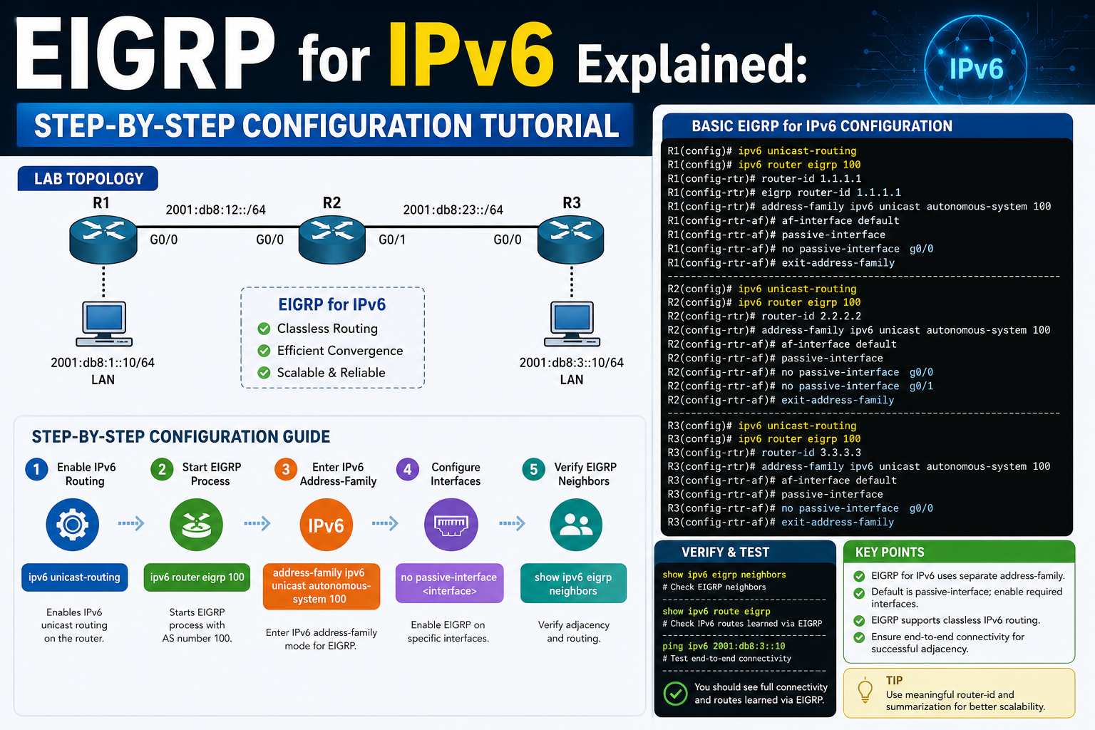
In modern networking environments, IPv6 has become the standard addressing system designed to replace the limitations of IPv4. One of the most widely used dynamic routing protocols that supports IPv6 is Enhanced Interior Gateway Routing Protocol, commonly known as EIGRP. When implemented correctly, EIGRP allows routers to automatically share routing information, adapt to changes in the network, and maintain efficient communication between devices without manual intervention.
In this scenario, the focus is on implementing EIGRP for IPv6 between two Cisco routers, referred to as R1 and R5. These routers are directly connected through their Fast Ethernet interfaces, forming a small but functional network topology. The purpose of this setup is not only to establish connectivity but also to demonstrate how IPv6 routing information can be dynamically exchanged using EIGRP.
Unlike static routing, where each route must be manually configured, EIGRP allows routers to learn about networks automatically. This is particularly useful in environments where scalability and adaptability are important. In this case, we are working entirely within an IPv6-only environment, meaning there is no reliance on IPv4 at any stage of configuration or communication. This ensures a modern approach aligned with current networking standards.
The topology also includes an additional component: a loopback interface on R1. This loopback will act as a stable and always-available network endpoint. It will be advertised into the EIGRP topology, and its successful appearance on R5 will confirm that routing is functioning correctly.
Preparing the IPv6 Environment and Enabling Routing Capabilities
Before any routing protocol can function in an IPv6 network, the routers must be configured to support IPv6 forwarding at a system level. By default, many Cisco devices do not enable IPv6 packet forwarding, meaning they can assign IPv6 addresses but will not route traffic between interfaces unless explicitly configured.
To activate IPv6 routing capability, each router must be placed into global configuration mode. Once inside this mode, the IPv6 unicast routing function is enabled. This step is essential because it allows the router to process and forward IPv6 traffic between interfaces rather than treating each interface as an isolated endpoint.
On both routers, R1 and R5, enabling IPv6 routing is the foundational requirement. Without this, even correctly configured interfaces will not be able to communicate across the network. This step essentially transforms the router from a simple endpoint device into a functional IPv6 router capable of handling dynamic routing protocols such as EIGRP.
At this stage, no routing protocol is yet active. The system is simply being prepared to support IPv6 communication. This separation of preparation and protocol configuration is important because it ensures that the underlying IPv6 infrastructure is stable before introducing dynamic routing behavior.
Designing the IPv6 Addressing Structure for the Topology
A well-structured addressing scheme is critical for any network implementation. In this topology, a simple IPv6 addressing plan is used to clearly demonstrate connectivity and routing behavior between R1 and R5.
The link between the two routers is assigned a single IPv6 subnet. R5 is given an address ending in ::5, while R1 is assigned an address ending in ::1 within the same /64 network. This shared prefix allows both routers to recognize that they belong to the same directly connected network segment.
In IPv6, the /64 prefix is extremely common and represents the standard subnet size for most network interfaces. It allows a large number of interface identifiers while maintaining efficient routing structure. Each router interface receives a globally unique address within this subnet, ensuring proper communication.
In addition to the physical interface addressing, a loopback interface is created on R1. This loopback is assigned a separate IPv6 subnet and is used as a stable logical network endpoint. Unlike physical interfaces, loopbacks are always active as long as the router is operational. This makes them ideal for testing routing protocols because they do not depend on physical connectivity.
The loopback will later be advertised through EIGRP so that R5 can learn about it dynamically. This will serve as a validation point for the entire configuration process.
Configuring Physical Interface Connectivity Between Routers
Once IPv6 routing capabilities are enabled and addressing is planned, the next step is to configure the physical interfaces connecting R1 and R5. These interfaces are Fast Ethernet ports that provide the direct communication path between the two routers.
On R5, the Fast Ethernet interface connected to R1 is assigned its IPv6 address within the shared subnet. After assigning the address, the interface is activated to ensure it begins sending and receiving traffic.
Similarly, on R1, the corresponding Fast Ethernet interface is configured with its IPv6 address in the same subnet. This ensures both routers are logically connected on the same network segment.
At this stage, both interfaces are still operating only at the Layer 3 addressing level. No routing protocol is active yet, meaning the routers can communicate directly but do not share dynamic routing information.
To verify that basic connectivity exists between the two devices, a simple connectivity test is performed using IPv6 echo requests. If the configuration is correct, R1 should successfully reach R5 and vice versa. This confirms that the physical link is operational, the IPv6 addressing is correct, and the interfaces are properly enabled.
This step is critical because routing protocols depend entirely on underlying connectivity. If basic communication fails, EIGRP will not function correctly.
Understanding the Role of Loopback Interfaces in IPv6 Routing
A loopback interface plays an important role in routing protocol testing and stability. Unlike physical interfaces, a loopback is a virtual interface that is always operational as long as the router itself is running. This makes it highly reliable for testing routing behavior.
On R1, a loopback interface is created and assigned a unique IPv6 address within a separate subnet. This address does not depend on any physical connection and remains stable even if physical interfaces go down.
The purpose of introducing this loopback is to simulate a network that exists beyond the directly connected link between R1 and R5. When this loopback network is advertised into EIGRP, it should be learned by R5 through dynamic routing updates.
This provides a clear verification mechanism. If R5 can see the loopback network from R1, it confirms that EIGRP is functioning correctly, neighbors are established, and routing information is being exchanged properly.
Loopbacks are commonly used in real-world networks for router identification, testing, and management purposes. They provide a consistent endpoint that is independent of physical topology changes.
Introduction to EIGRP for IPv6 and Its Behavior
EIGRP for IPv6 is a dynamic routing protocol designed to efficiently exchange routing information between routers in an IPv6 network. It operates similarly to its IPv4 counterpart but includes important differences in configuration and operation.
One of the key distinctions is that EIGRP for IPv6 does not use the traditional network statement found in IPv4 configurations. Instead, it is enabled directly on interfaces. This means that each interface participating in EIGRP must be explicitly configured to run the protocol.
Another important characteristic is that EIGRP for IPv6 operates under an autonomous system number. In this scenario, autonomous system 100 is used. This number identifies the EIGRP domain and ensures that routers participating in the same system can exchange routing information.
EIGRP uses a sophisticated algorithm known as the Diffusing Update Algorithm, which allows it to calculate the best path to a destination efficiently. It also maintains backup routes, ensuring fast convergence if a primary route fails.
However, before EIGRP can begin exchanging routes, it must be properly enabled on both the router and the relevant interfaces. This dual-level activation is essential for proper operation in IPv6 environments.
Enabling EIGRP for IPv6 on Router Interfaces
After basic IPv6 connectivity is established, the next step is to enable EIGRP on the participating interfaces. On R1, the Fast Ethernet interface connected to R5 is configured to run EIGRP under autonomous system 100.
Instead of using a global network command, EIGRP is activated directly under the interface configuration. This ensures that only selected interfaces participate in routing updates, providing greater control over routing behavior.
The same configuration is applied to the loopback interface on R1. By enabling EIGRP on the loopback, the router is instructed to advertise this network into the routing domain. This allows other routers, such as R5, to learn about the loopback dynamically.
At this stage, however, enabling EIGRP on interfaces alone is not sufficient. The routing process itself must also be activated at the router level. Without this, EIGRP will not fully function or exchange routing information.
This separation between interface-level activation and process-level activation is a key difference in IPv6 EIGRP configuration compared to older IPv4 implementations.
Activating the EIGRP Routing Process and Assigning Identity
Once EIGRP has been enabled on the relevant interfaces, the routing process itself must be activated on the router. This is done within the IPv6 routing configuration mode for EIGRP under autonomous system 100.
By default, the EIGRP process is in a shutdown state. This means that even if interfaces are configured correctly, no routing information will be exchanged until the process is manually activated. Therefore, the administrator must explicitly enable the routing process to allow EIGRP to function.
In addition to activating the process, each router must be assigned a unique router identifier. This identifier is typically written in a dotted decimal format and serves as a unique label for each router within the EIGRP domain.
The router ID plays an important role in route selection, loop prevention, and neighbor identification. Without a properly configured router ID, EIGRP cannot operate correctly.
Once the routing process is enabled and the router ID is assigned, the router is fully prepared to participate in EIGRP for IPv6 operations.
Initial Connectivity Verification Before Full Routing Exchange
Before fully validating EIGRP behavior, it is important to confirm that basic network communication is working at both the interface and protocol preparation levels.
At this stage, routers should already be able to reach each other through direct IPv6 connectivity. This ensures that physical interfaces are operational and correctly configured.
However, routing of additional networks, such as loopbacks, will not yet be visible on the remote router until EIGRP neighbor relationships are fully established in the next stage of configuration.
This separation between connectivity testing and routing verification helps isolate potential configuration issues. If connectivity fails at this stage, the problem is likely related to addressing or interface configuration rather than routing protocol behavior.
If connectivity succeeds, it confirms that the foundation for dynamic routing has been correctly established, allowing EIGRP to operate effectively once fully enabled on both routers.
Establishing EIGRP for IPv6 Neighbor Relationships Between Routers
Once IPv6 connectivity is confirmed between the two routers, the next critical stage in implementing EIGRP for IPv6 is the formation of neighbor relationships. These relationships are the foundation of all dynamic routing updates in EIGRP, as routers cannot exchange routing information unless they first recognize each other as trusted neighbors.
In a simple topology consisting of R1 and R5, the process of neighbor discovery begins automatically once EIGRP is enabled on the participating interfaces and the routing process is active. The routers begin sending multicast Hello messages over their IPv6-enabled interfaces. These messages serve as periodic signals that announce their presence to other EIGRP-enabled devices on the same network segment.
When R1 receives a Hello message from R5, and R5 receives one from R1, both routers evaluate whether they share compatible EIGRP parameters. These parameters include the autonomous system number, interface configuration, and basic protocol settings. If all conditions match, the routers form an adjacency, which is a formal neighbor relationship that allows routing information exchange.
This adjacency is not just a simple acknowledgment of connectivity. It represents a synchronized state where both routers agree to share and process routing updates in a structured manner. Without adjacency, EIGRP cannot function, even if physical connectivity is fully operational.
The process of forming this relationship is automatic but highly structured. It ensures that only routers within the same routing domain exchange information, preventing accidental or unauthorized route sharing across incompatible networks.
Understanding EIGRP Hello and Hold Timers in IPv6 Networks
The neighbor discovery process in EIGRP relies heavily on Hello and Hold timers. These timers control how often routers send Hello packets and how long they wait before considering a neighbor unreachable.
Hello packets are small, periodic messages sent between routers to maintain awareness of each other’s presence. In a stable IPv6 Ethernet environment, these messages are typically sent at regular intervals. When a router receives these messages consistently, it maintains the neighbor relationship as active.
The Hold timer represents the maximum amount of time a router will wait without receiving a Hello packet before declaring the neighbor unreachable. If this timer expires, the adjacency is broken, and routing information from that neighbor is removed from the topology table.
In the context of R1 and R5, these timers ensure that both routers maintain a continuous and reliable understanding of each other’s availability. If either router becomes unavailable or the link between them fails, the lack of Hello packets triggers a rapid recalculation of the routing topology.
This mechanism is essential for fast convergence, one of the key advantages of EIGRP. Instead of waiting for long timeout periods, the protocol quickly detects changes and adapts the routing table accordingly.
The Role of the EIGRP for IPv6 Process Activation
Unlike traditional IPv4 EIGRP configurations, where routing is often enabled globally through network statements, EIGRP for IPv6 requires explicit activation of the routing process. This process remains in a disabled state until manually enabled by the network administrator.
Once activated, the routing process becomes responsible for managing all EIGRP-related activities, including neighbor formation, topology exchange, and route computation. However, even after activation, the process does not automatically begin advertising routes unless interfaces are also configured to participate in EIGRP.
This separation between interface-level participation and process-level activation provides a more granular level of control. It ensures that only intended interfaces contribute to routing decisions, reducing unnecessary overhead and improving network stability.
In the R1 and R5 topology, activating the routing process allows both routers to begin exchanging routing information once their interfaces are correctly configured. Without this step, even correctly configured interfaces would remain isolated from the EIGRP domain.
Building and Maintaining the EIGRP Neighbor Table
Once adjacency is established, each router maintains a neighbor table. This table contains detailed information about directly connected EIGRP neighbors, including their router IDs, interface information, and timing details.
The neighbor table is dynamic and continuously updated. If a neighbor becomes unreachable, it is immediately removed from the table. Similarly, if a new neighbor appears on the network, it is added automatically once adjacency is formed.
In the R1 and R5 environment, each router will maintain a single neighbor entry corresponding to the other device. This entry confirms that the EIGRP relationship is active and stable.
The neighbor table plays a crucial role in ensuring that routing updates are exchanged only between valid and trusted devices. It prevents unnecessary processing of routing information from unknown or unauthorized sources.
This structure is particularly important in larger networks, but even in small topologies like this one, it ensures consistency and reliability in routing behavior.
Exploring the EIGRP Topology Table in IPv6
Beyond the neighbor table, EIGRP maintains a topology table that contains all known routes learned from neighbors. This table is more detailed than the routing table and includes all feasible paths to a destination, not just the best one.
Each entry in the topology table includes metrics that represent the cost of reaching a destination network. These metrics are calculated using a combination of factors such as bandwidth and delay. The router uses these values to determine the most efficient path for forwarding traffic.
In the R1 and R5 setup, once the loopback interface on R1 is advertised, R5 will learn about this network through its EIGRP topology table. It will then evaluate the metric and determine the best path to reach that loopback.
The topology table also stores backup routes known as feasible successors. These are alternative paths that can be used immediately if the primary route fails. This allows EIGRP to achieve extremely fast convergence without requiring recalculation from scratch.
This dual-layer structure of primary and backup routes is one of the key strengths of EIGRP compared to other routing protocols.
The Diffusing Update Algorithm and Route Calculation
At the core of EIGRP lies a powerful mechanism known as the Diffusing Update Algorithm. This algorithm is responsible for calculating the best path to a destination while ensuring loop-free routing.
When a router receives multiple possible paths to a network, it uses this algorithm to evaluate each route based on its metric value. The route with the lowest metric is selected as the primary path, while other valid paths may be stored as backups.
In the R1 and R5 topology, when R5 receives the advertisement of the loopback network from R1, it applies this algorithm to determine the best route. Since the topology is simple, the decision is straightforward, but the underlying process remains the same regardless of complexity.
The algorithm also ensures that routing loops do not occur by enforcing strict feasibility conditions. A route can only be considered a backup if it meets specific criteria that guarantee loop-free behavior.
This mechanism allows EIGRP to maintain stability even in large and complex networks with multiple redundant paths.
Advertising IPv6 Networks Through EIGRP Interfaces
In EIGRP for IPv6, networks are not advertised using traditional network statements. Instead, each interface must be individually configured to participate in the routing process.
When an interface is enabled for EIGRP, it automatically begins advertising the IPv6 network associated with that interface. This includes both directly connected physical interfaces and logical interfaces such as loopbacks.
In the R1 configuration, the Fast Ethernet interface and loopback interface are both participating in EIGRP. This means that both the directly connected network and the loopback network are advertised to R5.
On the R5 side, only the Fast Ethernet interface is required for EIGRP participation, as it will receive routing updates from R1 and install them into its routing table.
This interface-based approach provides greater flexibility and control over which networks are shared within the routing domain.
Router ID Selection and Its Importance in IPv6 EIGRP
Every router participating in EIGRP must have a unique router ID. This identifier is used to distinguish routers within the EIGRP domain and plays a key role in route calculation and loop prevention.
The router ID is typically assigned manually to ensure consistency and predictability. It follows a dotted decimal format, even in IPv6 environments, for simplicity and compatibility.
In the R1 and R5 topology, each router is assigned a distinct router ID. R1 uses one identifier, while R5 uses another. This ensures that each router can be uniquely identified during neighbor formation and route exchange.
The router ID is also used in the selection of successor and feasible successor routes. It helps prevent ambiguity when multiple paths exist between routers.
Without a properly configured router ID, EIGRP cannot operate correctly, as it relies on this identifier to maintain structured routing information.
Monitoring EIGRP for IPv6 Adjacency Stability
Once neighbor relationships are established and routing information begins to flow, it is important to monitor the stability of the EIGRP adjacency.
Stable adjacency means that Hello packets are being consistently exchanged, hold timers are not expiring, and routing updates are being successfully processed.
In the R1 and R5 setup, stability can be observed by ensuring that the neighbor relationship remains active over time without interruption. Any fluctuation in adjacency status may indicate underlying issues such as interface instability, misconfiguration, or timing mismatches.
Maintaining stable adjacency is essential for ensuring reliable routing behavior. Even minor disruptions can cause route recalculations and temporary loss of connectivity to advertised networks such as the R1 loopback.
Behavior of Route Propagation for the Loopback Network
Once EIGRP is fully operational, the loopback network configured on R1 becomes a key test of routing functionality. This network is advertised into the EIGRP domain and learned by R5 through dynamic updates.
When R5 receives the advertisement, it processes the route, calculates its metric, and installs it into its routing table. This allows R5 to reach the loopback interface on R1 without any static configuration.
The successful propagation of this route confirms that multiple components of EIGRP are functioning correctly. These include neighbor formation, topology exchange, metric calculation, and routing table installation.
This behavior demonstrates the core advantage of EIGRP: automatic learning and adaptation of network routes without manual intervention.
Internal Mechanisms Behind EIGRP Packet Exchange in IPv6
EIGRP uses several types of packets to maintain communication between routers. These include Hello packets, Update packets, Query packets, and Reply packets.
Hello packets are used to establish and maintain neighbor relationships. Update packets are used to share routing information. Query and Reply packets are used when searching for alternative routes in case of network changes.
In IPv6 environments, these packets are encapsulated and transmitted using IPv6 addressing, ensuring compatibility with modern network standards.
In the R1 and R5 topology, most communication occurs through Hello and Update packets due to the simplicity of the network. However, the underlying structure supports more complex interactions in larger topologies.
This packet-based communication system allows EIGRP to maintain efficient and reliable routing behavior even in dynamic environments.
Expanding EIGRP for IPv6 Stability Through Advanced Route Exchange Behavior
Once EIGRP for IPv6 is fully operational between R1 and R5, the network begins to behave as a dynamic system where routing information is continuously shared, evaluated, and updated. At this stage, the focus shifts from basic configuration and neighbor formation to deeper operational behavior, including how routes are exchanged, maintained, and optimized across the topology.
In this environment, R1 acts as the source of an additional network through its loopback interface, while R5 functions as a learning and verification point. The moment EIGRP stabilizes, both routers begin maintaining synchronized routing intelligence, ensuring that each device understands not only its directly connected networks but also remote networks discovered through EIGRP updates.
This continuous exchange is not random. It follows a structured process in which routers advertise only relevant changes rather than flooding the entire network with repetitive updates. This behavior is one of the key reasons EIGRP is considered efficient compared to older distance vector protocols.
When the loopback on R1 is introduced into the routing domain, it becomes part of this structured exchange. R5 learns about it through an update mechanism that ensures only necessary routing information is shared. Once installed in the routing table, this loopback becomes reachable through the dynamically calculated best path.
Deep Dive into EIGRP IPv6 Topology Maintenance
The topology table inside each router plays a central role in maintaining routing accuracy. It is more than a simple record of routes; it is a structured database that tracks all known paths, including primary and backup routes.
Each entry in this table contains multiple attributes, including the destination network, the successor route, feasible successors, and metric values. These elements work together to ensure that the router always has a reliable understanding of how to reach each destination.
In the R1 and R5 setup, the topology table on R5 will include the directly connected network shared with R1 as well as the loopback network learned from R1. These entries are constantly monitored for changes in reachability or metric updates.
If any change occurs in the network, such as interface failure or metric variation, the topology table is immediately updated. This ensures that routing decisions always reflect the current state of the network.
The stability of this table is essential for maintaining consistent routing behavior. Without it, routers would lack the necessary information to make informed forwarding decisions.
Successor and Feasible Successor Selection in IPv6 EIGRP
One of the most powerful features of EIGRP is its ability to maintain both primary and backup routes simultaneously. These are known as successor and feasible successor routes.
The successor route is the best path to a destination based on the lowest calculated metric. This route is actively used for forwarding traffic. The feasible successor, on the other hand, is a backup route that meets specific conditions ensuring it can be used immediately if the successor fails.
In the R1 and R5 topology, the route to the loopback on R1 will have a single successor path through the directly connected interface. However, in more complex environments, multiple feasible successors may exist.
EIGRP determines whether a route qualifies as a feasible successor by applying strict feasibility conditions. These conditions ensure that the backup route does not introduce routing loops.
This mechanism allows EIGRP to achieve near-instant recovery from network failures. If the primary route becomes unavailable, the router can immediately switch to the feasible successor without recalculating the entire topology.
EIGRP IPv6 Metric Calculation and Path Selection Logic
The metric system in EIGRP is designed to evaluate the quality of a path based on multiple factors. The most commonly used factors are bandwidth and delay. These values are combined to produce a composite metric that represents the cost of reaching a destination.
In the R1 and R5 environment, the metric calculation is relatively simple due to the direct connection between routers. However, even in this simple topology, the same calculation logic applies.
Each interface contributes to the overall metric based on its characteristics. Higher bandwidth links produce lower metric values, making them more favorable for routing decisions. Similarly, lower delay values also contribute to better metrics.
Once the metric is calculated, the router compares all available paths and selects the one with the lowest value as the successor route. This ensures that traffic always follows the most efficient path available.
This calculation process is continuous. If network conditions change, such as interface degradation or topology updates, metrics are recalculated and routing decisions are updated accordingly.
Query and Reply Mechanism in EIGRP IPv6 Operations
While simple topologies like R1 and R5 primarily rely on Hello and Update packets, EIGRP also uses Query and Reply packets in more complex scenarios.
When a router loses its successor route and no feasible successor is available, it enters an active state for that destination. In this state, it sends Query packets to its neighbors asking for alternative routes.
The neighbors respond with Reply packets, providing information about whether they have a valid path to the destination. This process continues until the router finds a valid route or determines that the destination is unreachable.
In the R1 and R5 topology, this mechanism is not heavily utilized due to the simplicity of the network. However, understanding it is essential for scaling EIGRP into larger IPv6 environments.
This query-based approach allows EIGRP to dynamically discover alternative paths without requiring manual intervention or complete routing table recalculation.
Convergence Behavior of EIGRP for IPv6
Convergence refers to the process by which all routers in a network reach a consistent understanding of the routing topology. EIGRP is known for its fast convergence compared to traditional distance vector protocols.
In the R1 and R5 setup, convergence occurs almost instantly due to the small size of the network. Once the loopback is advertised, R5 quickly learns the route and installs it into its routing table.
If a change occurs, such as interface failure or route modification, EIGRP reacts rapidly by recalculating affected routes and updating the topology table. This ensures that traffic is redirected without significant delay.
The speed of convergence is one of the primary advantages of EIGRP, especially in environments where uptime and reliability are critical.
Route Installation into the IPv6 Routing Table
Once EIGRP determines the best path to a destination, it installs the route into the IPv6 routing table. This table is used by the router to make actual forwarding decisions for incoming packets.
In the R1 and R5 scenario, the loopback network on R1 will appear in the routing table of R5 after successful EIGRP exchange. This confirms that the routing process is fully functional.
The routing table only contains the best available routes, unlike the topology table which contains all possible routes. This separation ensures efficiency in packet forwarding.
Each entry in the routing table includes the destination network, next-hop address, outgoing interface, and administrative information.
Once installed, these routes are used for all traffic forwarding decisions unless changes occur in the network.
Role of Administrative Distance in EIGRP IPv6 Routing Decisions
Administrative distance is a value used by routers to determine the trustworthiness of a routing source. Lower values are considered more reliable.
EIGRP has a default administrative distance that makes it more preferred than many other routing protocols. This ensures that EIGRP-learned routes are selected over less reliable sources when multiple routing options exist.
In the R1 and R5 environment, this ensures that the loopback route learned via EIGRP is preferred over any potential static or alternative routes, if they were present.
Administrative distance plays a silent but important role in ensuring consistent routing behavior across the network.
Maintaining EIGRP Stability in IPv6 Environments
Stability in EIGRP is achieved through continuous monitoring of neighbor relationships, routing tables, and topology changes. As long as Hello packets are exchanged and no disruptions occur, the network remains stable.
In the R1 and R5 topology, stability is relatively easy to maintain due to the simplicity of the design. However, even in small networks, minor misconfigurations can disrupt EIGRP behavior.
Interface shutdowns, incorrect addressing, or mismatched autonomous system numbers can all lead to loss of adjacency. When this happens, routing information is removed until connectivity is restored.
Maintaining consistent configuration across all participating devices is essential for long-term stability.
Behavior of EIGRP During Network Changes
When a change occurs in the network, EIGRP reacts dynamically. If a route becomes unavailable, the router immediately checks for a feasible successor. If one exists, it is promoted to the successor role without delay.
If no feasible successor exists, the router initiates the query process to discover alternative routes.
In the R1 and R5 setup, if the link between the routers were to fail, R5 would immediately lose access to both the directly connected network and the loopback network. It would then attempt to reestablish connectivity once the link is restored.
This adaptive behavior ensures that the network remains responsive to changes without requiring manual reconfiguration.
Final Observations on IPv6 EIGRP Operational Flow in a Simple Topology
In the R1 and R5 IPv6 EIGRP environment, the entire routing process flows through a structured lifecycle. It begins with IPv6 activation, followed by interface configuration, neighbor discovery, topology exchange, route calculation, and finally routing table installation.
Each stage builds upon the previous one, ensuring that routing information is accurate and reliable. The loopback interface on R1 serves as a key validation point throughout this process, confirming that dynamic routing is functioning correctly.
The interaction between neighbor tables, topology tables, and routing tables demonstrates how EIGRP maintains a synchronized understanding of the network. Even in a simple two-router setup, these mechanisms operate in full complexity, mirroring behavior found in large-scale enterprise networks.
Fine-Tuning EIGRP for IPv6 Behavior Through Interface-Level Control and Protocol Consistency
Beyond the core operation of EIGRP for IPv6, real-world implementations often require careful attention to how the protocol behaves at the interface level. Even in a simple topology like the one between R1 and R5, small adjustments in interface participation can significantly influence routing stability, convergence speed, and overall protocol efficiency.
One of the most important aspects of EIGRP for IPv6 is its interface-centric design. Unlike IPv4 implementations where routing advertisements could be broadly controlled through network statements, IPv6 relies heavily on explicit interface activation. This means every interface that participates in routing must be intentionally configured, ensuring precise control over which networks are advertised and which remain isolated.
This design reduces unnecessary routing overhead and improves security by preventing accidental route sharing. In the R1 and R5 setup, only the Fast Ethernet interfaces and the loopback interface on R1 are participating in EIGRP. This selective participation ensures that only relevant networks are exchanged between the routers.
Another important consideration is protocol consistency across interfaces. EIGRP for IPv6 requires that all participating interfaces operate under the same autonomous system. If even one interface is configured with a mismatched system identifier, adjacency formation will fail, and routing updates will not be exchanged.
Consistency also extends to timer synchronization. Hello and Hold timers must align closely between neighbors to maintain stable communication. While EIGRP is generally tolerant of minor differences, significant mismatches can lead to unstable adjacencies or frequent reconvergence events.
In addition, interface stability plays a crucial role in maintaining routing reliability. Physical interfaces that experience frequent up-and-down states can cause repeated EIGRP recalculations, leading to unnecessary load on the routing process. In contrast, loopback interfaces provide a stable anchor for routing advertisements, ensuring that at least one consistent network remains reachable even if physical links fluctuate.
The interaction between interface states and EIGRP behavior highlights the importance of designing networks with stability in mind. Even though EIGRP is highly resilient, its performance is directly influenced by the quality of the underlying interface configuration.
Finally, the overall behavior of EIGRP for IPv6 in this topology demonstrates how dynamic routing protocols rely on layered communication structures. From interface-level activation to topology exchange and route selection, each component works together to maintain an accurate and responsive routing environment.
Conclusion
The implementation of EIGRP for IPv6 between two Cisco routers, R1 and R5, demonstrates how modern dynamic routing operates in a structured and highly efficient manner. Even though the topology is simple, consisting of just two routers connected through Fast Ethernet interfaces and an additional loopback on R1, the underlying processes reflect the same principles used in large-scale enterprise networks.
At the foundation of the entire configuration is IPv6 enablement. Without activating IPv6 unicast routing, neither router would be capable of forwarding IPv6 traffic between interfaces. This step transforms the device from a basic endpoint into a fully functional IPv6 router. It is the essential prerequisite that allows all subsequent routing behavior to function correctly.
Once IPv6 forwarding is enabled, interface configuration becomes the next critical layer. Each router interface is assigned a unique IPv6 address within a shared subnet, establishing direct communication between R1 and R5. This step ensures that the physical and logical connectivity required for routing protocol exchange is in place. The addition of a loopback interface on R1 introduces a stable, always-active network that serves as a reliable test point for routing advertisement.
The transition from basic connectivity to dynamic routing begins with the activation of EIGRP for IPv6. Unlike older IPv4 implementations, EIGRP in IPv6 environments requires explicit activation at both the interface and routing process levels. This dual activation model provides greater precision and control, ensuring that only intended interfaces participate in routing updates.
Once enabled, EIGRP initiates neighbor discovery through Hello packets. This leads to the formation of adjacency between R1 and R5, establishing a trusted communication channel for routing exchange. The neighbor relationship is essential because it forms the foundation for all further EIGRP operations, including topology sharing and route calculation.
After adjacency is established, routers begin exchanging routing information and building their topology tables. This table is more than a simple list of routes; it is a structured database that stores all known paths, including primary and backup options. Through this mechanism, each router gains a complete view of available network destinations.
The Diffusing Update Algorithm then plays its role in selecting the best path to each destination. Metrics based on bandwidth and delay are calculated, and the most efficient route is chosen as the successor. Backup routes, known as feasible successors, are also stored to ensure rapid failover in case of network changes.
In this specific topology, the loopback interface on R1 becomes the key element used to validate the entire EIGRP configuration. Once advertised, it is learned by R5 through dynamic routing updates and installed into its routing table. This confirms that neighbor relationships, topology exchange, and route calculation are all functioning correctly.
Administrative distance and router ID assignment further enhance stability and clarity within the routing domain. These elements ensure that routing decisions are consistent and that each router is uniquely identifiable within the network. Without them, route selection and neighbor identification could become ambiguous, leading to potential inconsistencies.